CAPACITORS

What is a Capacitor?

A capacitor is an electronic device that stores energy in an internal electric field. It is a basic passive electronic component along with resistors and inductors. All capacitors consist of the same basic structure: two conducting plates separated by an insulator, called the dielectric. A voltage applied to the plates creates an electric field across the dielectric, which causes the plates to accumulate a charge. The charge remains after the voltage source is removed, allowing energy to be stored until the capacitor is discharged (allowing the stored energy to perform work).

What is Capacitance?

Capacitance is the amount of charge that can be stored at a given voltage by an electrical component called a capacitor.

What are the factors that affect capacitance?

The size of the conductive plates and the permittivity of the insulating dielectric material determine capacitance.

How are Capacitors Rated? And why is this important?

Capacitors are rated in capacitance, working voltage, tolerance, leakage current, working temperature, equivalent series resistance, etc.

What is the effect of capacitance?

The larger the capacitance of a capacitor, the longer it takes to charge and discharge. This means it takes more time for voltage to build up (charge) or fall (discharge). This makes capacitance useful for filtering out small voltage variations that last only a short length of time, i.e.. high-frequency transients.

What is parasitic capacitance and why is it important in electronic circuits?

Unintended (parasitic) capacitance exists between any two conducting materials – the closer in proximity and size, the greater the value. This must be factored into the design of a circuit as it can affect the speed at which it operates. For example, a large transistor may allow faster switching, but its larger size means a larger parasitic capacitance exists between its terminals and this may slow the speed of the circuit driving it.

Capacitor Circuit Model

The circuit model for a capacitor consists of the capacitive, inductive, and resistive elements.

The circuit model of a capacitor consists of a series resistive element representing the ohmic resistance of the conducting elements along with the dielectric resistance.

Effective Series Inductance (ESL) is the parasitic inductance in a capacitor or resistor.

Effective Series Resistance (ESR) is the resistive component of a capacitor’s equivalent circuit. A capacitor can be modeled as an ideal capacitor in series with a resistor and an inductor. The resistor’s value is the ESR.

WHAT IS CAPACITOR AGING? IS IT REVERSIBLE?

“Aging” refers to the natural process wherein X7R, X5R, Z5U & Y5V ceramic capacitors exhibit a drop in capacitance and dissipation factor over time. It is caused by a gradual realignment of the crystalline structure of the ceramic. To reverse this shelf life aging effect, the parts can be “deaged” by baking parts at +125ºC for 4 hours or ½ to 1hour at +150ºC. This will result in parts increasing in capacitance and returning closely to their original value. It should be noted that parts which are deaged and then subjected to temperatures above the curie point (typically +120ºC), such as soldering and temperature cycling, may shift up in value slightly.  As the temperature is later reduced below the Curie point, the capacitance gradually returns to its previous values. Aging occurs at a rate that decreases roughly linearly with the log of time. NPO/C0G and tantalum capacitors have a different molecular structure which is essentially immune to aging and therefore they remain quite constant with time.


The aging rates are somewhat proportional to the dielectric constant or permittivity of a materials and are typically expressed as a percent per decade hour (i.e. 1-10 hours, 10-100 hours, 100 – 1000 hours, etc. Aging occurs quickly at first and then much more slowly over time.  Maximum aging rates are as follows:
 

Maximum % Capacitance Loss/Decade Hour

X7R – 2.0%
X5R – 2.5%
Z5U – 7.0%
Y5V – 7.0%
(actual rates may be lower)
 

Because the capacitance changes rapidly just after deaging, capacitance measurements are delayed for 24 hours (referred to as “last heat”).

WHAT IS THE IMPACT TO VOLTAGE WHEN CAPACITORS ARE PLACED IN SERIES OR PARALLEL?

Parallel: When connected in parallel, the total capacitance is equal to the sum of the individual capacitance values. When connected in series, the total capacitance is lowered to the reciprocal level (exactly the opposite of resistors). For example, if three capacitors of values 1.0µF, 0.10µF, and 0.010µF are connected in parallel, the total capacitance would be:


C = C1 + C2 + C3 = 1.0µF + 0.10µF + 0.010µF = 1.11µF


The voltage rating of the parallel capacitors is only as high as the smallest voltage rating of the group, if they aren’t equal.  If they are equal, the voltage rating is the same as that of a single capacitor.


Series: If the same three capacitors are connected in series, add their reciprocal values, as follows:


1/C = 1/C1 + 1/C2 + 1/C3 = 1/1 µF + 1/0.1µF + 1/0.01µF = 1/0.009, therefore C = 0.0090µF


The voltage rating of the series capacitors is equal to the sum of the voltage ratings of the individual capacitors if they are the same value.  If the capacitors are of different values, and are used in an AC circuit, the voltage division will not be equal.


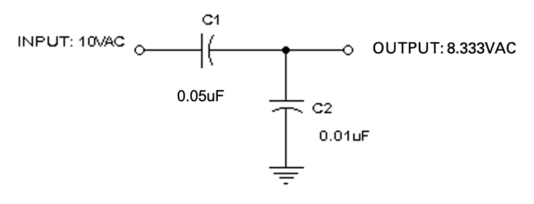
AC Voltage Divider: Capacitive dividers can be used with AC input signals.  Since a DC input voltage wouldn’t pass through the capacitors, the DC case isn’t relevant.  The formula for determining the AC output voltage of a capacitive divider is as follows:


Vout = (Vin * C1) / (C1 + C2)


Example:  In the following circuit, the output voltage would be:  Vout = (10VAC x 0.050µF)/(0.050µF + 0.010µF) = 8.333VAC.  The output voltage is typically not dependent on the input frequency however, if the reactance of the capacitors is too low at the frequency of interest, the output current capability will also be very low.

Schematic

WHAT POLARITY IS HTE LONG LEG OF CAPACITOR?

On a Tantalum capacitor with radial leads (RCD TR Series), the long leg lead is always the positive or anode lead on the capacitor. The capacitor should also have the polarity marked on the capacitor. The exception to this is a non-polar capacitor (such as RCD’s CEA or CER Series ceramic capacitors) which will have no polarity marking on them. Non-polar capacitors may still have different lead lengths but this does not indicate any polarity orientation.

WHY DID THE CAPACITANCE VALUE CHANGE WHEN I APPLIED VOLTAGE TO THE CERAMIC CAPACITOR?

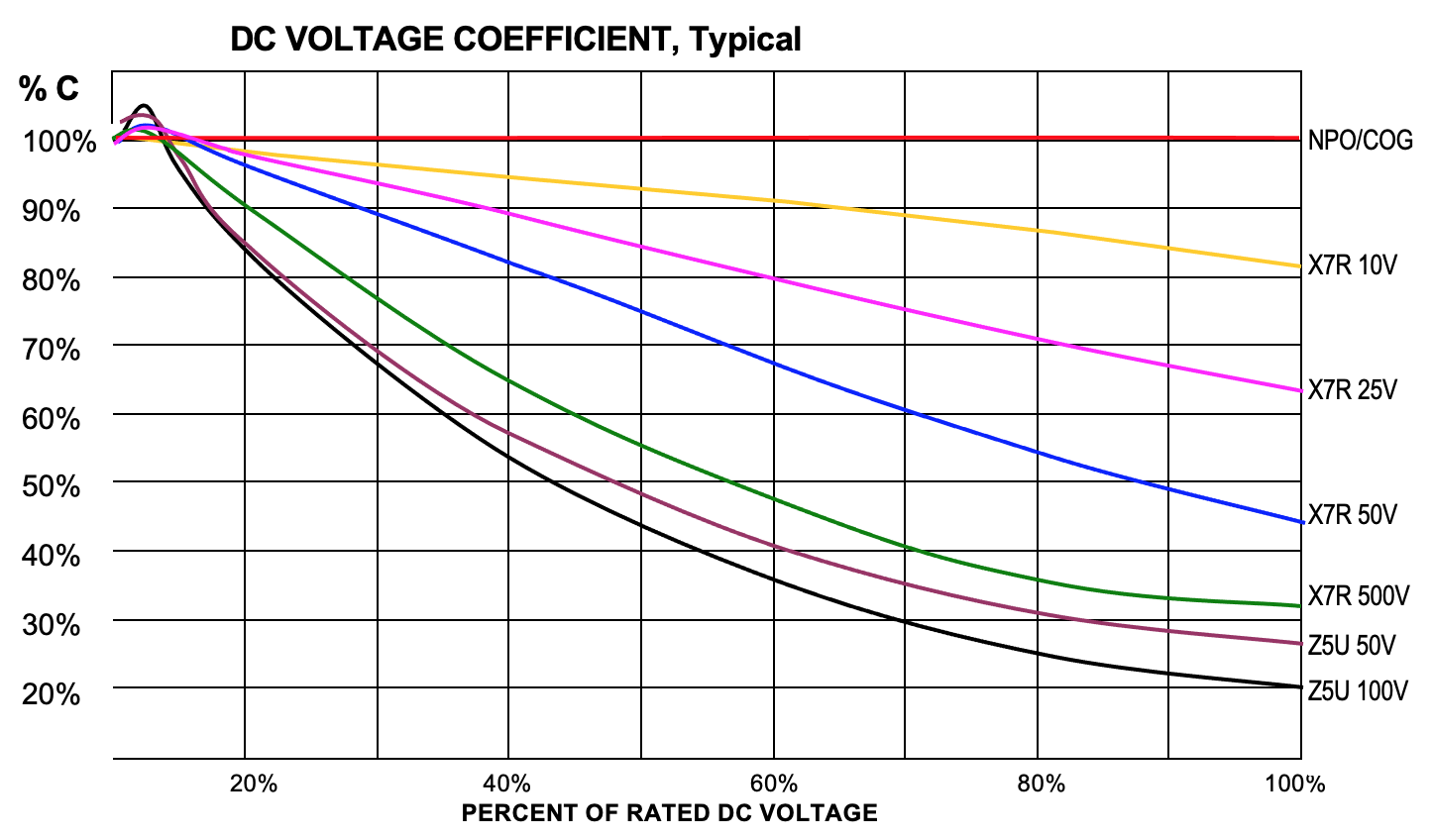
Class 2 (X7R, X5R) and Class 3 (Y5V,Z5U) ceramic capacitors have problems not seen in Class 1 (NPO, COG) and film capacitors, including very poor temperature drift, high voltage-coefficient-of-capacitance and, high voltage-coefficient-of-dissipation factor (all of these are different for AC and DC), high frequency-coefficient-of-capacitance and a significant aging rate. Class 2 capacitors are best suited for coupling (DC blocking) and power supply bypassing.  They are primarily used in linear applications where performance and stability are of no great concern.  Class 3 capacitors should be used only for DC blocking and bypassing. The change in capacitance due to aging, temperature coefficient, and voltage coefficient must be taken into account whenever using Class 2 or 3 caps, especially class 3.  For best performance, use the parts at a low percentage of rated voltage. Applied voltage affects some properties so much that these capacitors are normally characterized at no more than 1 volt AC or DC. The table below shows what happens to capacitance when DC voltage is applied to various ceramics.  Capacitance vs. AC voltage generally has the opposite result (capacitance increases in value).   The numbers are approximate and vary somewhat with capacitance value. Graph

WHAT ARE THE TYPICAL FAILURE MODES OF CERAMIC CHIP CAPACITORS?

Ceramic capacitors are quite reliable. Failures typically result from voltage overloads or mechanical stress. The most commonly reported cause of field failures is high leakage (i.e., low insulation resistance) usually attributable to microcracks. When high energy levels are involved, microcracks can result in catastrophic failure. Under lower energy levels, damaged chips could continue to function for a long time.  Circuit test equipment will generally only identify those caps with high leakage levels. The reason for this is because the crack (or more specifically the air gap in the dielectric resulting from the crack), acts as a capacitor, making the damage difficult to detect. Since the voltage stress is concentrated in the area of the crack, this degrades the bulk resistivity, propagating even higher leakage levels over time especially in conditions of high temperatures and humidity.


Causes of cracks are typically due to mechanical stresses (excessive board flex, shock/vibration impact from handling, testing, depanelization, pick & place pressure, etc.), or thermal stresses (excessive soldering temperature or duration, thermal expansion/mismatch). In addition to user-related problems
Failures can also result from:

  • improper surface conduction, i.e., entrapped flux under chip or external surface contamination (more common with “No clean” systems) result in shunt leakage paths.
  • Fractured terminations
  • High surge currents
  • Aging – the capacitance value typically decreases through the normal aging process on X5R, X7R, Z5U, Y5V dielectrics.
  • Voltage and temperature changes can also have a fairly significant affect on the capacitance value of these dielectrics resulting in parts which have temporarily shifted beyond the nominal tolerance band
  • Open/intermittent solder joints due to tombstoning, poor PCB or chip solderability, leaching of the termination plating, chip or solder placement, cold solder joints, etc.
  • Improper handling or processing by the capacitor manufacturer can result in cracks or voids in dielectric.
  • Improper labeling or sorting by manufacturer

Note: it is not uncommon for the nodal analysis by ICT (In-Circuit Test) equipment to falsely characterize a chip capacitor as being non-compliant when another component is actually at fault.

WHAT DOES EACH CHARACTER IN "X7R", "Z5U", ETC., ACTUALLY REPRESENT?

The 3-character designations describe how a particular type of ceramic capacitor will perform over its intended temperature range. See breakdown in following table. The code was assigned by the Electronic Industries Association (EIA).


Lowest Operating Temperature

Highest Operating Temperature

Maximum Allowable Capacitance Shift from 25ºC Readings

Without DC Bias

At 50% rated V

X = -55ºC

5 = 85ºC

R = +15/-15%

R = +15/-15%

Z = +10ºC

7 = 125ºC

S = +22/-22%

S = +22/-22%

Y = -30ºC

8 = 150ºC

U = +22-56%

U = +22-56%


V = +22/-82%

V = +22/-82%

Precision capacitors are identified as COG (also known as NPO) which indicates a worst case temperature coefficient of 30PPM/ºC (0.003%/ºC).

HOW DO I SPECIFY A CAPACITOR IF I DON'T KNOW RCD'S PART NUMBER?

  1. Advise competitor’s part number or, if unavailable, advise whether it is a conventional thru-hole part (axial, radial or disc) or surface mount.
  2. Advise construction (ceramic, tantalum, etc.). If unknown, go to #3.
  3. Advise capacitance value (0.01µF or micro farads, 10nF or nano farads, etc.).
  4. Advise capacitance tolerance (“Z “or +80/-20%, 10%, 5%, etc.).
  5. Advise voltage rating (50V, 6V, etc.).
  6. Advise dielectric (if a ceramic). NP0/C0G, X7R, Y5V, Z5U, X5R, etc.
  7. Advise of any special electrical requirements (low ESR, low profile, marking, etc.).
  8. Advise of any special lead-forming if thru-hole.
  9. Advise of any special packaging requirements (bulk, tape/reel, etc.).